Authors:
Stanislav Viktorovich Solsky, JSC «B. E. Vedeneev All-Russian Research Institute», Saint Petersburg, Russia
Ilya Grigoryevich Zelensky, LLC «ID Engineering», Saint Petersburg, Russia
Introduction
Russia has extensive experience in transporting and storing by-products from mineral-processing plants. The development of technologies for transporting and storing these products has been closely linked to the development of the mineral-processing industry. The industry began expanding actively around the 16th century, when artisanal production gave way to industrial-scale deposit development. Over time, production volumes and technical requirements changed, and storage methods improved.
The need for new technical solutions for transporting and storing by-products from mineral-processing plants is driven by increased raw-material processing volumes, the relocation of Russian mineral-processing centres to remote areas with severe climatic conditions, improved mineral-extraction technologies and stricter environmental requirements. It is important that the current regulatory framework should facilitate, rather than hinder, the introduction of advanced solutions into projects under development. Design, construction, operation and regulatory development should proceed in synchronisation, drawing on positive experience in each area.
Modern environmental requirements for the design and operation of man-made storage facilities for industrial soil masses are therefore of major importance and are becoming decisive across all industries, including mineral processing.
For storage facilities for soil masses, especially hydraulic-fill facilities, priority must be given to compliance with environmental legislation, particularly water legislation, regarding the depletion and pollution of surface and groundwater and the geological environment.
The impact of storage facilities on surface water includes:
- abstraction of part of the surface runoff for industrial water supply;
- withdrawal of substantial catchment areas for the storage facility and mineral-processing operations;
- direct discharge into a surface water body of seepage through the base and retaining dams, with hydrochemical parameters exceeding permissible discharge standards.
In some cases, this results in almost complete degradation of the surface water body and/or substantial changes to its water regime.
These impacts require surface runoff to be managed on the industrial site and adjacent territory, and seepage and drainage runoff to be contained. Part of the contaminated runoff may be directed to the facility’s recirculating water system; the remainder should be sent to treatment facilities and then discharged into the water body in accordance with the approved permissible-discharge standard through a control point and flow meter.
This requires justification and registration of the right to use the water body.
The impact of storage facilities on groundwater occurs through areal seepage via the base, the base and body of retaining structures, and drainage systems. Groundwater conditions are monitored under a production and environmental monitoring programme approved by environmental authorities, using a network of monitoring wells and special regime observations with the relevant reporting.
These impacts require eliminating or minimising the possibility of contaminated seepage entering underground aquifers. This is achieved by waterproofing the storage-facility base with soil materials (inert clayey and loamy materials and, where justified, silty-clay fractions of the stored materials) and geosynthetics (geomembranes and concrete mats), and by installing special seepage-control screens and/or cut-off curtains along retaining dams and side abutments. These may be watertight systems, such as various types of in-ground cut-off walls (trench walls, secant piles, grouting curtains, frozen-soil curtains, geosheet-pile curtains, etc.), or drainage curtains providing gravity drainage or mechanical pumping. Depending on the conditions, a combination of seepage-control and drainage systems is often effective.
Contaminant concentrations in seepage are generally much higher than in surface wastewater, increasing the cost of treatment facilities. Therefore, it is advisable to direct the maximum possible volume of seepage to the recirculating water system.
A serious environmental challenge is dust generation from storage facilities and waste dumps, which pollutes the air, soil cover and surface water bodies over extensive adjacent areas. This requires organisational and technical measures, from wetting to stabilising or covering potentially dusty surfaces. The task is difficult because dust generation is seasonal and the affected areas are extensive.
From an environmental perspective, it is increasingly important to substantiate and recognise the status of stored soil materials as waste. Unfortunately, current design guidance and waste legislation almost invariably classify all stored soil materials as waste, although they often are not waste and, in terms of their properties and chemical composition, do not differ from inert materials.
Soil masses may be regarded as sources of inert materials for constructing earth structures, backfill mixtures for mine workings and technogenic deposits of minerals not fully extracted.
Soil-material storage technology
The main technological systems for storing soil materials and waste are outlined below, together with issues related to the behaviour of hydraulic-fill geotechnical masses.
The main current schemes for storing soil materials and mineral-processing waste are:
- Hydraulic transport as slurry:
- hydraulic filling with a settling pond and recirculating water supply. The hydraulic-fill beaches of each retaining-dam lift form the base for the next lift. The stored soil materials or waste serve as construction materials for these beaches and the retaining dams;
- hydraulic filling with a settling pond and recirculating water supply, with the retaining dam constructed in advance for the entire filling period entirely from imported material;
- paste storage without recirculating water supply or a pond. This method requires special equipment and a relatively complex paste-production process. Irreversible water losses during paste placement must be considered.
- Road or conveyor transport:
- transport of semi-dry soils to dumps or storage facilities.
Combined methods are also used, with hydraulic transport and truck-delivered semi-dry materials used in the same basin. The storage method may also change during operation: a hydraulic-fill facility may be converted into an embankment facility, etc.
In some cases, thickening the slurry before hydraulic transport is effective. It can reduce electricity consumption and pipeline and main-pump costs. When materials contain large quantities of fine silty-clay fractions, thickening may be necessary to control hydraulic filling and water clarification.
However, thickening significantly reduces the process stability of hydraulic transport and storage and increases the total number of equipment units, affecting the reliability of these systems. It also creates dependence on flocculant supplies.
Paste thickening is achieved at a moisture content above 70%. Paste is intermediate between thickened and semi-dry material. It cannot be dewatered without special equipment, but can still be transported hydraulically. This can substantially reduce capital costs and construction times and increase useful capacity compared with slurry storage facilities.
Hydraulic-fill storage facilities are of greatest interest because, as noted above, the by-products of concentrate extraction at mineral-processing plants serve as construction materials.
If the stored material consists mainly of sand and sandy-loam fractions, placement and compaction present no major difficulties, unlike silty-clay particles. Unlike sand, these materials enter the hydraulic dump saturated with water and dewater and compact over a long period. Under continuous hydraulic filling, they have increased pore pressure and therefore reduced soil shear strength.
These factors increase the risk of failure not only of the retaining dam but also of the entire hydraulic-fill mass, since these elements cannot be physically separated in a hydraulic-fill structure.
Soil consolidation
Given the prevalence of silty-clay fractions in stored soil materials and waste, their consolidation is critical to the reliable and safe operation of hydraulic-fill storage facilities.
The importance of consolidation-related problems in hydraulic-fill masses can be illustrated by two major examples of accident consequences.
In 2010, an alumina plant 160 km from Budapest, Hungary, suffered a dam failure that released more than one million cubic metres of toxic red mud. More than 40 km2 was affected and 10 people were killed.
In 2019, a tailings-storage failure at an iron-ore operation in Brumadinho, Brazil, killed 259 people.
To substantiate existing and future methods, technologies and technical solutions for managing consolidation in hydraulic-fill geotechnical masses, some general information is provided below.
Soil consolidation is an important factor that must be considered in the design, construction and operation of industrial, hydraulic, transport and civil structures. Consolidation is directly related to the multiphase structure of soil. Theories describing this process and other rheological properties form the basis of engineering forecasting.
Soils, the most common construction materials for hydraulic-fill soil masses, combine the conventional phases of matter—solid, liquid and gas—forming a three-component system.
Their strength and other physical and mechanical properties depend on the combined interaction of these elements and vary widely.
Construction-related problems caused by foundation consolidation have long been studied. The first equation describing this process with variable porosity and permeability was proposed by the Russian hydraulic engineer N. N. Pavlovsky. In 1925, the Austrian geologist Karl Terzaghi solved a particular one-dimensional problem. In the 1930s, Soviet soil scientist N. M. Gersevanov developed an incomplete system of equations for solving a spatial problem.
The theory of seepage consolidation of soils was further developed in the work of Russian scientist V. A. Florin. His ideas and calculations formed the basis of modern soil mechanics. The three-component model proposed by V. A. Florin was later used in the work of Y. K. Zaretsky, L. V. Gorelik, M. Y. Abelov, P. L. Ivanov and other scientists. Their methods are used in the design of hydraulic structures, offshore oil facilities and other structures on weak soils.
The following types of soil consolidation are distinguished:
Natural consolidation, caused by the pressure of overlying layers. It ends after a certain period. The resulting stresses are called historical stresses. If current soil stresses coincide with historical stresses, the soil is normally consolidated. If current stresses are lower, the soil is overconsolidated, as occurs when loading decreases, for example, during glacier melting.
Primary consolidation, caused by water migration through pores as their volume decreases under load. The consolidation value is determined from the graphs below, with the degree of consolidation ranging from 0 to 100%.
Secondary consolidation, in which compaction continues through creep of the solid particles, or soil skeleton, which was not considered in the previous case. The secondary-process soil consolidation coefficient is calculated to determine settlement.
Consolidation differs from simple compression in that the latter does not involve a change in water volume.
The main soil characteristics affecting settlement rate are:
- ability to transmit water under pressure (permeability);
- structure (properties of the constituent particles);
- pressure exerted by the liquid on pore walls;
- ability of the skeleton to deform over time under load;
- compressibility of mineral particles, water and air in the soil pores;
- loading scheme;
- geological structure;
- predominance of one phase or another, for example, the presence of air reduces the consolidation coefficient and the rate of excess pore-pressure equalisation.
In highly water-saturated sandy soils, pore-water drainage occurs faster and the consolidation coefficient is therefore higher because the spaces between solid particles are relatively large. Shear deformation in sandy and fragmental rocks results from mutual particle displacement and the breakdown of contacts between particles.
In clays, volume deformation causes dense repacking of particles surrounded by a liquid film. Consolidation rate is mainly determined by the type of structural bonds and the load. Water-colloid bonds give clay soils elasticity—the ability to recover after load removal. Post-compaction strengthening is related to the renewal of these bonds if internal stress has not exceeded structural strength. Since clay-soil pores are much smaller, consolidation occurs more slowly.
The most difficult soils to forecast are structurally unstable soils, whose deformation is affected by additional external factors: thawing of frozen soils, decomposition of organic matter in peat and peaty soils, loess wetting and increasing salinity. In peat, for example, seepage consolidation declines rapidly, while settlement continues for a long period.
As noted above, during consolidation of the solid fraction, pore water must be released and pathways and zones created to relieve pore pressure; in other words, engineering methods must be used to activate consolidation of soil masses.
With a draining base and permeable retaining dams, this problem is absent, particularly in sandy soils. In addition, in sandy soils, water is expelled from the soil mass into the settling pond.
The situation is quite different when the stored material consists of silty-clay fractions and a waterproof screen is installed in the storage basin. A clay mass can be viewed as a sequence of waterproof layers preventing pore-water movement. Without special measures, water cannot be removed from such soil.
The following measures are used to address this problem:
- use of suitable reagents (flocculants and rheological modifiers);
- installation of structural elements that accelerate soil-mass consolidation (drains);
- use of storage technologies that promote soil consolidation in the mass (dispersed hydraulic filling, layer-by-layer placement, etc.).
These measures may be combined. For example, reagents used for hydraulic transport enable denser placement of solid material. Layer-by-layer hydraulic filling with a holding period for each layer also increases placement density. Compaction of the stored material improves its waterproofing properties, reducing seepage impacts on groundwater and surface runoff almost to zero. It also substantially increases storage volumes within the same basin dimensions.
Practical examples of hydraulic-fill storage facilities for soil consolidation
We are currently improving and developing methods and technological techniques based on traditional and modern geotechnical materials to ensure predictable consolidation of large hydraulic-fill geotechnical masses. Two examples of solving soil-mass consolidation problems at specific hydraulic-fill facilities are presented below.
Mineral-processing plant in Zabaykalsky Krai
After one mineral-processing plant in Zabaykalsky Krai was commissioned, the thickening process could not be properly adjusted for a long time. Plant products were placed in the underwater zone and spread across the entire basin. No soil was deposited in the beach zone; it flowed to lower elevations into the settling pond. The tailings facility filled up, but there was no base for raising the next lift. Urgent and effective measures were required to consolidate the soil in the beach zone.
To solve the problem and create a reliable base for the next lift, the rheological modifier REOMAKS was used to change the strength and deformation properties of the hydraulic-fill material. Within one month, a base was formed near the dam and construction of a new lift began. No visible deformation or other adverse effects have been observed in this section of the structure.
Storage facility design for mineral-processing plant product in the Republic of Buryatia
A project for a mineral-processing operation under construction in the Republic of Buryatia involved a complex combination of factors:
- hydraulic-fill storage facility;
- geomembrane waterproofing screen in the storage-facility base and retaining dam;
- stored soil mass consisting of more than 90% clay fractions.
Consequently, special technical solutions were required to enable pore water to escape from the soil mass.
The basin and upstream slope of the starter dam were screened with polymer sheet (geomembrane) and other geocomposite materials manufactured by TEXPOLIMER Group. The differences between the proposed screen design and the design specified in SN 551–82 are:
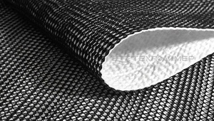
Use of the geocomposite mat “Hydromat 2D” (STO 56910145-005-2011) instead of sand as the bedding layer and soil cones (mounds) instead of a continuous sand bedding layer. “Hydromat 2D” provides both protection and continuous drainage, collecting and conveying water beneath the screen. “Hydromat 2D” consists of an 8–10 mm thick three-dimensional mesh with diamond-shaped polymer ribs bonded on one side to nonwoven geotextile. Under load, “Hydromat 2D” retains its thickness and compresses only slightly, allowing it to serve as a cushioning layer that levels the surface and prevents geomembrane damage.
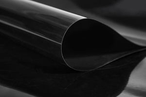
Use of a polymer sheet (geomembrane, TU 2246-001-56910145-2014) made of high-density polyethylene (HDPE) as the main seepage-control element. The geomembrane sheets were joined into a continuous covering by thermal welding, forming a double seam with a test channel. This technology improves the screen’s reliability and durability and enables instrumental testing of seam strength and integrity.
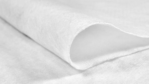
Use of a protective covering layer made of nonwoven geotextile (STO 56910145-009-2014) with a surface density of 600 g/m2 and soil cones spaced at 2.5×2.5 m instead of a continuous protective sand layer at least 0.3 m thick. High-density, high-strength geotextile was selected because of the substantial load from the stored product. The construction technology is staged and layer-by-layer, preventing vehicles and equipment from driving over the installed geomembrane. This significantly reduces screen-damage risks during construction, shortens the work period and reduces inert-material volumes while ensuring the required reliability, safety and durability.
On the sumps and retaining-dam slopes, a geomembrane textured on both sides (type 4/2 according to TU 2246-001-56910145-2014), 1.5 mm thick, was used to increase adhesion between the geomembrane and the soil base, as the texture provides a higher friction coefficient. This also improves adhesion of the protective soil layers placed over the geomembrane on the inclined slopes. A smooth geomembrane of the same thickness—1.5 mm (type 1 according to TU 2246-001-56910145-2014)—was used to waterproof the basin.
Drains remove water from soil while retaining the soil itself. They may be horizontal, vertical or inclined, or take the form of drainage berms or prisms, made of natural or artificial materials. Reverse filters are installed to prevent suffosion and clogging. At this facility, a soil-mass drainage system made of natural materials was provided as an inclined drain on the upstream slope of the retaining dam.
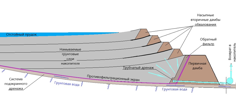 The drainage structure consists of several layers of rock soil of different fractions, from sand to gravel, checked for suffosion resistance and permissible hydraulic gradient. Filtered water is collected in a collector made of perforated plastic pipe. The collector is discharged through steel drainage pipes passing through the dam body into a drainage tank downstream. From the drainage tank, seepage is pumped back to the settling pond by a drainage pumping station. The drainage tank was designed with a geomembrane screen manufactured by TEXPOLIMER Group, similar to the storage-facility basin screen.
A network of horizontal drains was installed beneath the basin screen to remove clean water emerging from the sides. The drains discharge downstream. During construction, they convey construction flows.
This technical design of the dam and storage-facility basin is intended to address several tasks:
- prevent recirculating water from leaking from the basin into the foundation soils and through the dam body downstream, ensuring the facility’s environmental safety with respect to natural waters;
- promote consolidation of the clay mass formed by storage of mineral-processing products, ensuring retaining-dam stability and improving the reliability and safety of hydraulic structures (HS).
Conclusions
Today, substantial attention in the construction and operation of HS at mineral-processing facilities is focused on finding new effective solutions to minimise the adverse environmental impact of storage facilities. This is particularly important where storage facilities are located close to areas inhabited by large numbers of people.
One area for developing technical solutions to ensure the reliable and safe operation of hydraulic-fill geotechnical masses is the activation and management of consolidation in stored soil masses consisting of silty-clay fractions. Given increasing storage volumes, declining mineral content in raw ores and the substantial share of HS construction and operating costs, this task may become a priority when determining the profitability and economic efficiency of many mineral-processing operations.
Original article: S. V. Solsky, I. G. Zelensky. “Current Structural Solutions for Storage Facilities for Soil Materials and Waste from Mineral-Processing Enterprises” // Hydraulic Engineering. 2022. No. 3. pp. 56–61.